

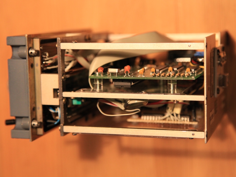
Radio management panel or shorter RMP is one of those panels with their own electronics meaning it uses ARINC bus to communicate. Making it work directly is basically beyond my current knowledge. I was thinking if maybe Arduino controller board could work with ARNIC interface but I don’t have the energy to tackle that… I couldn’t even find the proper back pin-out. Well I did found some data on the 28V connection but nothing happened, not even smoke or sparks!

So if I don’t figure something else these are just a nice paperweights. Well I also got this radio tagged as beyond repair and this might also be one of the reason it wasn’t working! Who knows, it was in really poor condition?
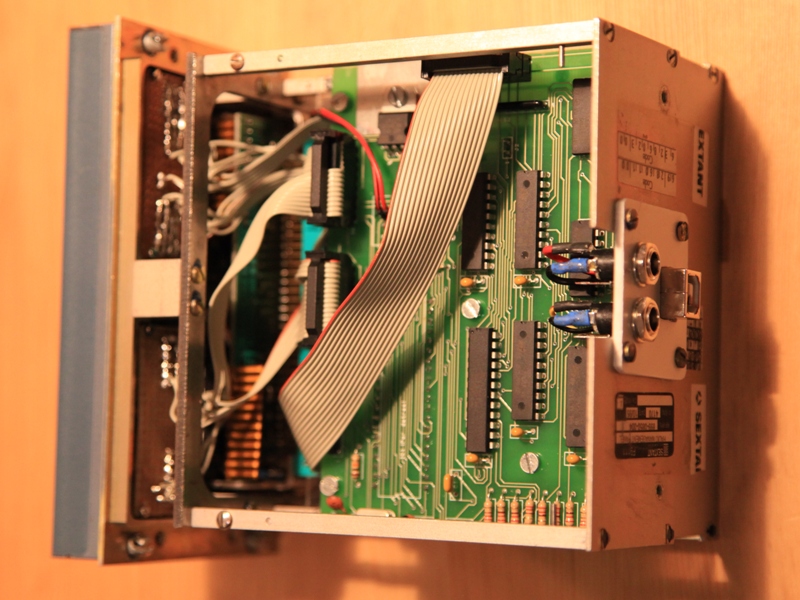
It was a difficult decision but taking internal electronics out and using only front panel seemed the easiest and only way. I know, it is sad to modify those original parts but I wanted to continue. If ARINC interface ever happens I will regret it then!
I was essentially left with only front panel and it was time to figure out the panel back pin rail.
The idea was to use 7 segment displays and OC input/output IO board. It sounded good though the problem I later encountered was the quantity of all the wires at the back, I didn’t like that mess. I also had some second hand OC radio panels with convenient USB connection. That could work, I took the main OC radio circuit board, seven segment displays and a made a board with ULN’s for selection dots to illuminate. After figuring the OC RPM board pin-out I started wiring.
OC board would fit almost perfectly in RMP housing. I needed to sand only a millimeter or two of one side. I liked this solution with only USB and and power connections at the back. Of course I had to reposition the USB connector to the rear where also connectors for backlight power and selection dots are.
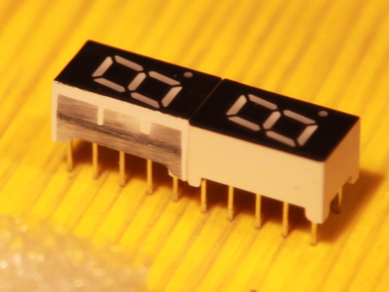
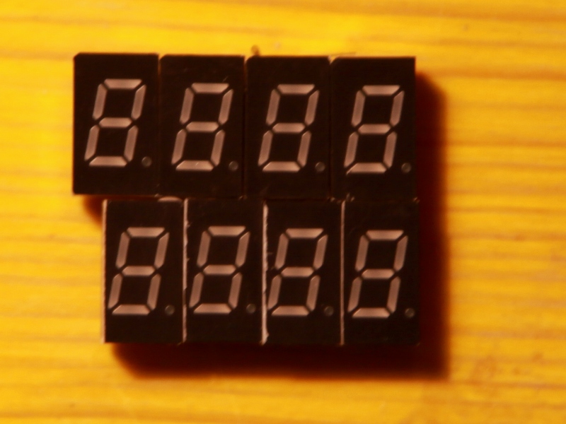
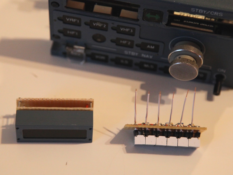
Another story where frequency displays. Display housing is pretty tight and won’t properly fit all segment displays on a sockets PCB! In fact digit sections are too wide and I had to sand each one a millimeter of the side to get them closer together to fit the housing.

A bit of refurbishment with a fresh paint job on metal parts. Now this works and looks incredibly cool, still got some touch up painting to do. Now I need to repeat all that for the second RMP and maybe even the third!
To make it work I also used SIOC and OC RMP script, which I had to modify a bit to work as it should. Of course OC RMP panel has its flaws. The most superficial one is that sixes and nines are displayed without the upper and lower section! I told them about that and they have not changed anything to this day, how hard can that be, I don’t understand?!
Recent Comments