

With original parts and panels you will come to a question of power as these parts also need “original” power. With A320 there are mainly three power figures 5VAC, 28VDC and 115VAC 400Hz going in and out of transformers.
Korry indicator switches uses four bulbs (MS24515-718), two for each legend segment. One bulb is rated 5V 115mA, which means 230 mA for lighting one legend segment. This relatively high current is a problem as most interface boards provide only low currents for leds. In my case with OC IO card each exit provides 5V with 25 mA only.
How to get that higher “bulb” current from IO cards? I thought the answer lies in relay boards but that turned out to be too expensive, bulky and loud. Then I diverted to transistors but also I couldn’t find any simple solution. Later a friend from our Virtual aviation club, also a cockpit builder helped me and introduced a Darlington transistors array or chip named ULN2003A. We talked about this on one of our monthly meetings.
This chip was a key to get those higher currents, almost as the Holy Grail! ULN chips can be used where there is requirement for high current or voltage ratings which cannot be provided by other interfacing devices.

This ULN2003A is an array of seven Darlington transistors capable of 500 mA, 50 V per output.
Basically the low current IO card output signal triggers / grounds higher current circuit lighting Korry bulbs. All you need is sufficient power supply like old PC power supply (5V, 25A).
IO card outputs connects to IN pins 1 to 7 and are grounded on pin 8. On the other side you connect the wires from Korry ground to OUT pins 10 to 16 which are also grounded through pin 8 when associated input pin is active. The pin 9 will turn all outputs on, sort of light test. I hope this is understandable?
I had some problems defining maximum chip current as specifications are written very unclear about that. It says 500 mA per output is possible but it doesn`t clearly say what is maximum chip current? I think 500 mA is also the maximum current for whole chip! This means one Korry per chip if you want to be on a safe side, two legends per 220-230 mA. I guess I could connect two Korrys per ULN (cca 0,9A). It is good that Airbus has all lights out philosophy. There are not many cases where there are more than ten Korrys lit at the same time. That is possible to distribute among the chips in a way that (normal procedures) they do not exceed the 500 mA limits.
I did tested one chip with all 7 outputs with 220mA so that 1.55A current ran through it for 5 minutes. The chip obviously got quite hot 50-60°C but was still under max specified temp of 70°C. I guess heat sinks would help lower the temp but they are probably more expensive than the chip! I’d rather buy more of these.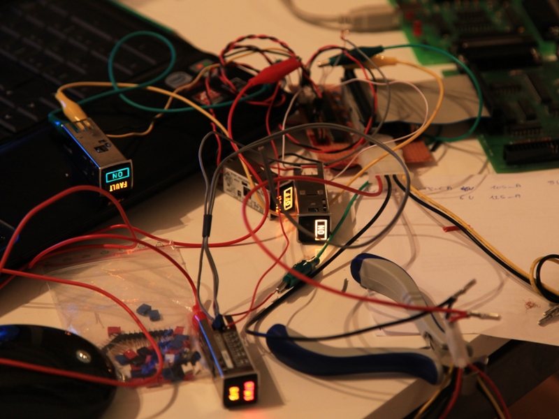
I quickly found out that Korry bulbs are very bright at 5V. With the PC power supply you also get 3.3V power so I also tried this and got satisfactory results. Bulbs were still bright enough and the current decreased a bit which is also welcome.
I only later learned that with ANN LT switch (DIM, BRT, TEST) on overhead panel 25VU you not only test but also dim the Korry annunciators. What’s funny is that in DIM positions bulbs are supplied with 3V and in BRT with 5V, as if I knew.
The next interesting thing was that AUTO LAND, MASTER WARNING and CAUTION lights together with ACP panel get 6.3V in BRT and 4.3 in DIM. (ATA 33)
Recent Comments