If you are using OEM (original equipment manufacturer) panels you will basically come across two types. Panels that have their own internal electronics and use ARINC 429 bus interface communication like FCU, ACP, RMP, ATC, CDU,… and switching panels without internal electronics, using Korry switches and knobs (overhead panels). They all have canon plugs with a number of pins at the end. You can bypass them by cutting internal wires and making your own connections for panel backlight, switches and indicators or you can find the correct pin-out and use the original wiring witch sometime is not as straightforward as it seems. Both methods have their own good and bad aspects.

Cutting original wires will mean “straight” connection to input/output boards but endless soldering and wire confusion. By cutting or gutting ARINC panels you will also loose all internal logic and panel functions! All that needs to be replaced by re-programming these functions or using dedicated software.
Finding the right pin-outs will require going into Aircraft Schematic Manual (ASM), Aircraft Wiring Manual (AWM) and maybe even Aircraft Maintenance Manual (AMM) along with multimeter, using resistance and continuity test. With switching panels you can also encounter a kind of internal switching logic that can make connections to input/output boards somewhat interesting. In some cases some programing will be necessary to overcome that switching logic.
On the left side of the page you can find a menu with my pin-out diagrams. I am not immune to mistakes so there could be some errors and typos on those diagrams (if you see any mistake or typo please let me know)! Therefore use them with a measure of common sense and don’t forget you are using pin-out diagrams at your own risk! In no event shall I be liable to any user or third party for any damages whatsoever resulting from the use or inability to use this website or the material and content provided on this site. Please don’t use diagrams commercially and publicate or distribute them without permission.
There are also other pin-out combinations possible due to redundancy that are not described on my diagrams.
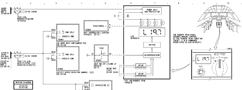
All the pinouts won’t work without proper power and interface. With A320 panels there are basically two powers figures 5VAC and 28VDC. Panel backlight bulbs need 0 – 5V depending on the intensity, Korry switch indicators need 3 – 5V, also depending on the intensity you want DIM or BRT. Panels that have their own internal electronics usually need 28VDC, a few will also need 115 VAC – 400Hz power to work.
With ARINC 429 panels until recently, there was no real solution unless you were electronic and programming whiz. Fortunately now you can find quite some vendors making ARINC 429 in/out boards and related programs. That makes the use of these panels quite easy if you add 28VDC. However it gets more complicated if panel also needs 115 VAC – 400Hz, the tricky part is getting this sort of power.